After creating a cabinet, the program shows the empty six faces of the
cabinet in the specified dimensions. A right button mouse click on any
of these walls brings up a popup menu, which allows to add some
elements to the wall.
The following elements are available:
- Drivers
- Vents
- Interior walls
- Inner casings
Every element is positioned on the wall in a wall coordinate system
with origin at the lower left corner of the wall.
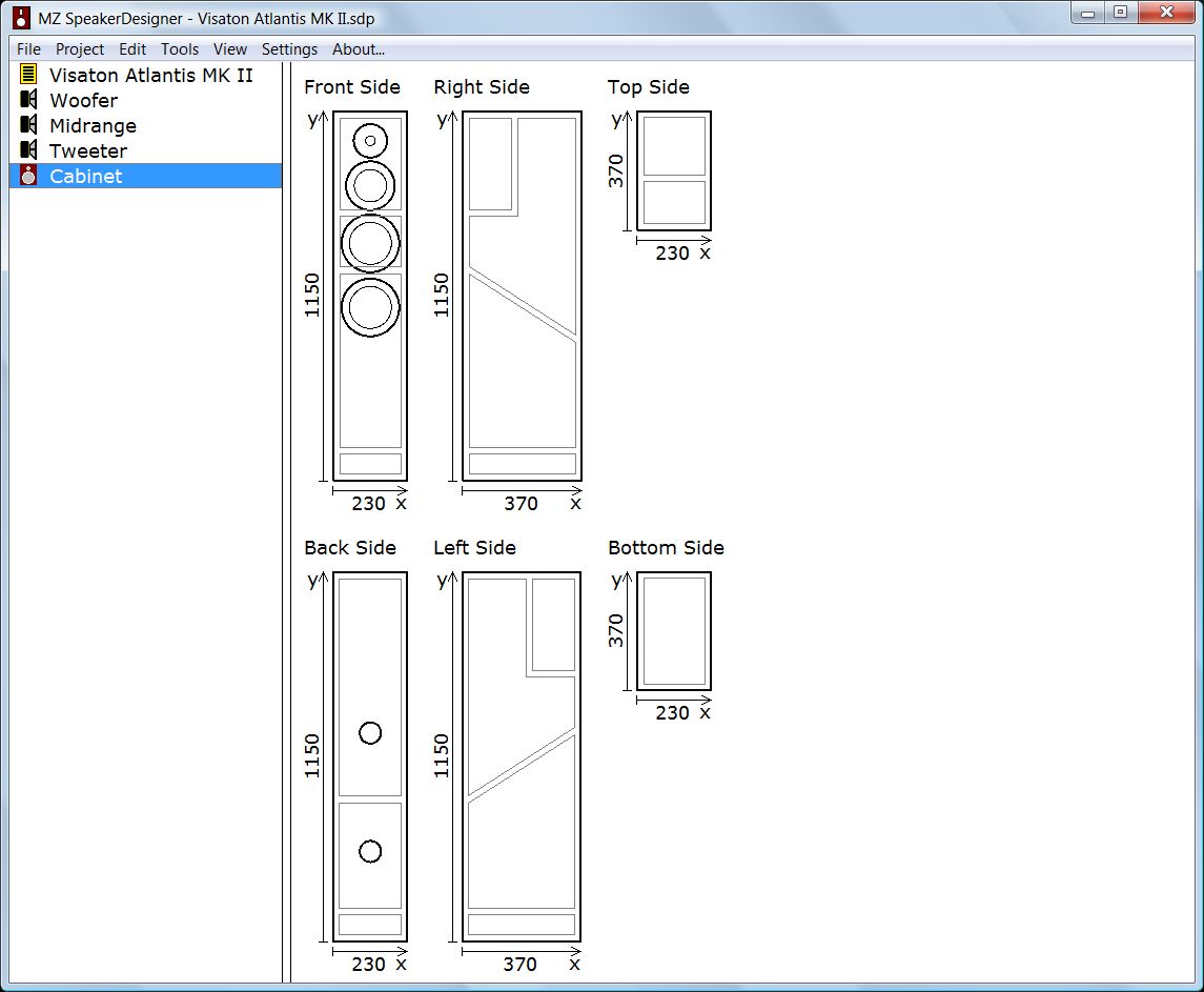
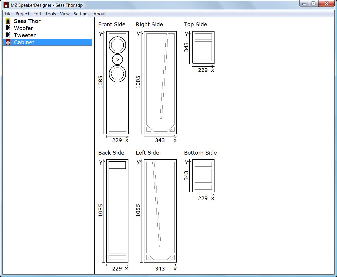
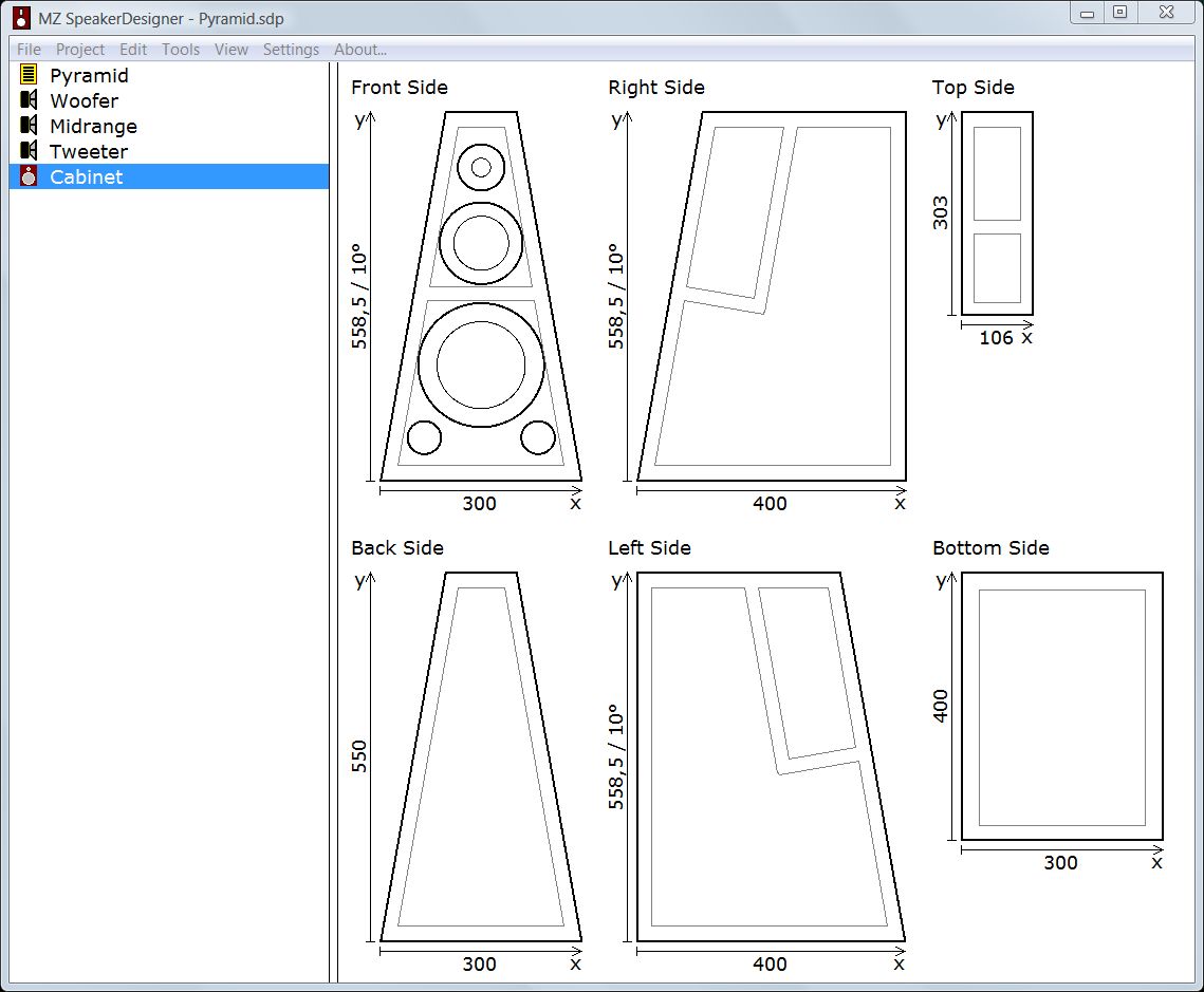
In this way it is possible to construct a wide range of different
speakers. The examples below show how realistic cabinets can be defined
using some wall elements. But beside the nice look, all major data
required for a accurate speaker simulation is given as well. MZ
SpeakerDesigner automatically extracts the following information from
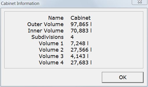
the cabinet:
- The number of internal volumes and their dimensions.
- The drivers and vents being assigned to a particular volume.
- The type of rear configuration for every driver (closed, vented or
transmission line).
- The size of the baffle and the position of each driver.
|